Hey guys,
I searched the forums and found advice on how to remove the gauge needle (pull straight out), however it's not coming off and I do not want to break it.
I'm trying to change some of the LEDs on my instrument cluster so I'm trying to get these off.
Anyone have experience taking these off or can help, it would be greatly appreciated.
thanks!
Reply 1 : DIY: Instrument Cluster LED
Contact catric69. He might know.
Reply 2 : DIY: Instrument Cluster LED
thanks dce, I just figured it out. I'll be posting a DIY with pics later

Reply 3 : DIY: Instrument Cluster LED
This is a DIY for changing the Instrument Cluster LEDs. I only did the gauges, high beam and fog light LEDs, however there are much more you can do.
Tools needed:
- Phillips Screwdriver
- Flathead Screwdriver (2)
- 10mm Ratchet Wrench
- 1 small, sharp object, such as razor tip, small flat head screw driver, toothpic
- Soldering Iron (preferably 2)
- no-clean solder
- no-clean soder wick (optional)
- Steady Hands
- Tweezers (optional)
- Grounding wrist or ankle straps or equivalent device
- Digital Multimeter
2. There are two connectors in the back of the unit that you need to remove. The smaller one has shorter wires, so remove that one first, then you can pull the unit out a little further to get the inner connector

Each has a small plastic tab in the middle of the connector, push it in and pull the connector out.

3. There are 10 screws on the back of the cluster that need to be removed.

6. After removing the screws, turn the unit right side up and start un-latching the clear plastic cover. It has several hooks (4 on the bottom, 1 on each side and 2 on top). After the clear plastic cover is off, start un-latching the black plastic cover (5 hooks on bottom, 1 on each side and 4 on top).

7. After you have the black plastic cover off, the unit should come right out of the white plastic back. Now you are just left with the Logic Board, a plastic part and instrument face plate.
I could not pull off the needles by hand, so I had to use two flathead screw drivers and place them under the needle from two opposite directions and wedge it up. Read below for instructions on how to remove the needles.

If you are pulling these off by hand, make sure that you are not bending the needle in any direction other than pulling directly upwards. The reason why is there is small needle in the cluster that you do not want to bend. Bending this needle will most likely damage your gauge.

8. SMALL NEEDLES: After removing the needle, there is a small black plastic piece that you need to remove before the face plate can come off. Take something very thin like a razor tip or a tooth pic and gently push it in between the small white tab and the black plastic ring and wedge the black ring off.

9. LARGER NEEDLES: On the larger gauge needles, the small black plastic ring is slightly different. it has three small plastic hooks. Again use whatever thin tool you took the first plastic ring off and place it in between the small white area and the black plastic hook and push the hook inwards. It should pop out as shown below.

10. After all needles and plastic rings are off of the cluster, you can how take the face plate off. Once the face plate is off, you will notice the two small LCD displays at the bottom, these need to come off. Gently lift both up at the top just slightly enough to get over the small tabs. Then you will need to lift on the bottom two corners of the unit to remove the leads from the logic board.

Below is a picture of the LCD screens and a visual of why you have to be very careful about lifting the top of the screen away from the tabs. You do not want to bend these leads.

11. After the LCD screens are off, you should flip the unit over and remove the small white connect from the logic board. If you don't do this, the board will be hanging from it. After it is removed you can remove the logic board from the white plastic cover.

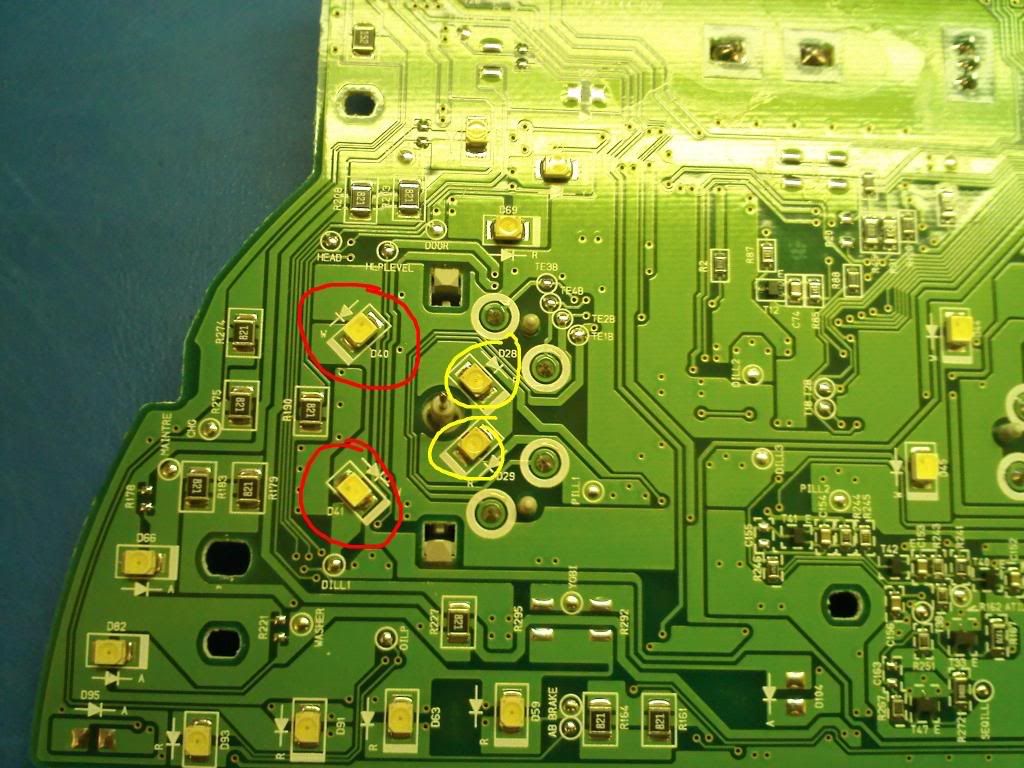
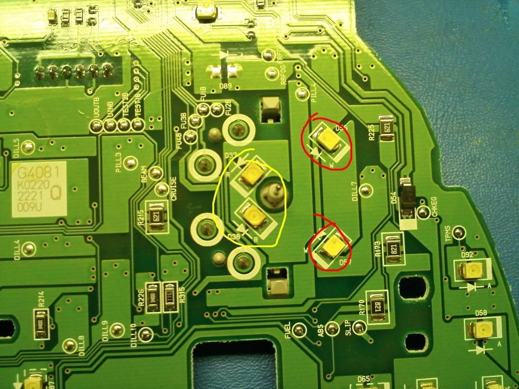
Here's a few pictures of LEDs that I changed. They are also on dcemureviews' post about the cluster panel on his Master LED DIY thread.
http://www.toyotanation.com/forum/sh...0&postcount=17
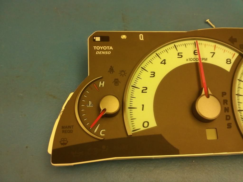
Tempature Gauge LEDs (needles are circled in yellow but I did not change these, only the gauge LEDs circled in red)
Tachometer

Speedometer

Fuel
12. Now the fun part, soldering! In order to take these off, you can use either two soldering irons, one soldering iron with tweezers, or one soldering iron with solder wick. I choose two soldering irons between that's what i'm used to doing and it's quicker.
Once you take the LED off, make sure you clean the trace (metal pad on logic board) with solder wick to take off the excess solder. It's not likely to happen, but you do not want a solder bridge under your LED because that will create a short and cause you problems.
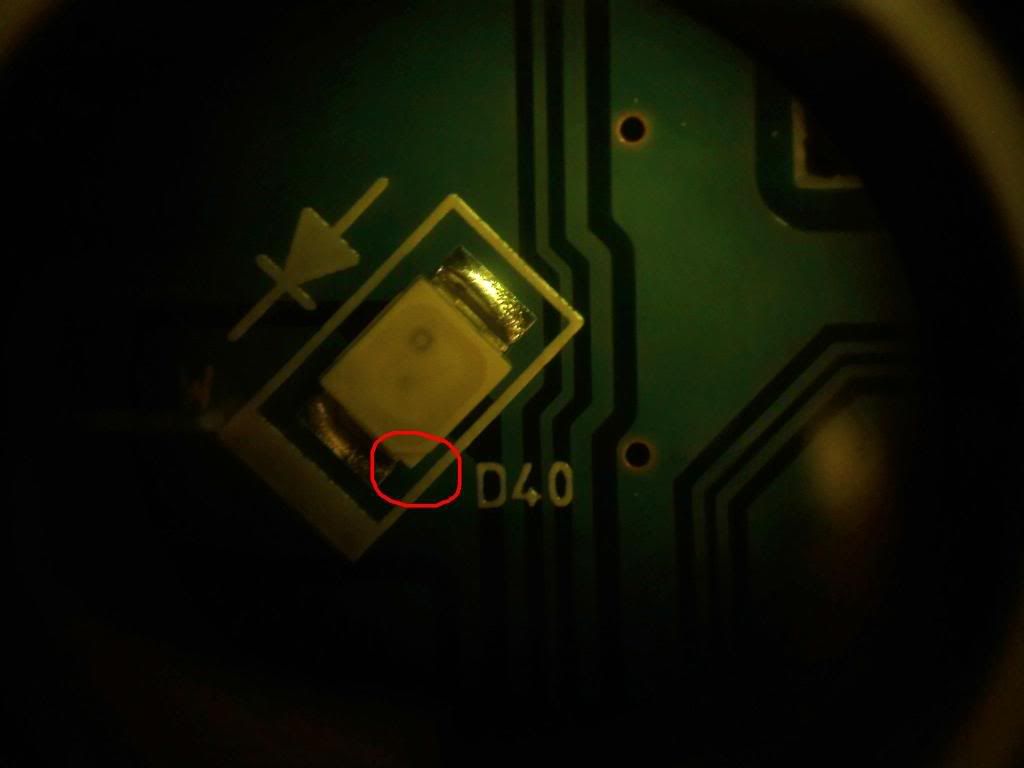
When placing the new LED in, take note of the polarity of the logic board. There will be a diode symbol next to the LED telling you which way the current flows. You will want to place the side of the LED with the small triangle in the corner on the same side as the arrow is pointing, as shown below.

After you have finished soldering, I would suggest taking a digital multimeter and checking each one of your LEDs to make sure there is no short. A short can be two things, either a bad LED or a solder bridge, so it's best to just replace any LED that is shorted (and cleaning the traces before placing a new on one). Remember, more solder is not always good. You want just enough solder to hold the LED to the trace.
13. After you have checked everything, start putting everything back together in reverse order that you took it apart. One thing to make note of is the LCD screens, you want to make sure that when you push them in, you are pushing down at the bottom of the LCD while holding the other side to make sure the LCD's leads are fully secure in the connector.

Another note is that when you place the needles back on, make sure that you twist the needle counter-clockwise for the needles that spin clockwise (tachometer, speedometer), and clockwise for the needles that spin counter-clockwise (temperature, fuel). If you put too much pressure you will break the mechanism that keeps the needle from going too far. If the needle passes the lowest threshold of the gauge, then you need to take off the needle and adjust it so that the farthest counter-clockwise (tach, speed) or clockwise (temp, fuel) you can go is the bottom of the gauge. if you do not do this, your needles may be slightly off.
After the needles are on, I would suggest re-attaching the black plastic piece and before going any further, re-connect your cluster to your car. Turn on your car and check to make sure your needles are in the correct positions. If everything looks good, then take out the cluster and finish putting everything back together, if it is not, then re-adjust the needles. My gas needle is slightly too high, so I will have to adjust it next time I go to replace some more LEDs this week.
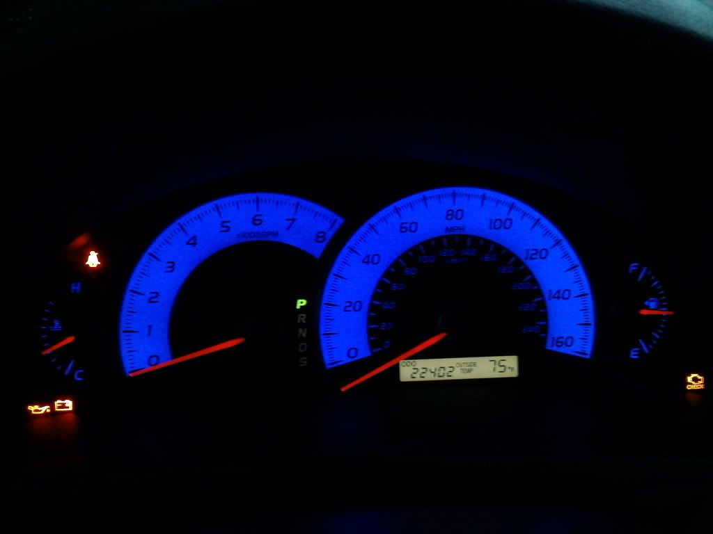
And there you have it, the end result is a nice bright display in your color of choice, mine is blue. I turned down the brightness in my picture so that you could see more of the blue, otherwise it comes off as much whiter.

Reply 4 : DIY: Instrument Cluster LED
wanna do mine? hehe its a xle cluster though. awesome job.
Reply 5 : DIY: Instrument Cluster LED
Nice work =)
Could you possibly tell me the color of the original LED's? just want to know what color it is. Thanks
Reply 6 : DIY: Instrument Cluster LED
i want to change the needles color or the whole needles, i really dont feeling the orange needles, i want it while or blue. anyone know how to do it?
Reply 7 : DIY: Instrument Cluster LED
Very nicely done.
Reply 8 : DIY: Instrument Cluster LED
nice write up...i'm adding it to the DIY sticky

Reply 9 : DIY: Instrument Cluster LED
Quote:
|
Originally Posted by Netforcer 
Nice work =)
Could you possibly tell me the color of the original LED's? just want to know what color it is. Thanks |
 I believe they are white. If I have some time at work this week, I'll rig up something to test the LEDs to see what color they are. I kept all the LEDs that i removed and labeled them, so I can tell you what color is where.
Quote:
|
Originally Posted by Kenny_el2003
i want to change the needles color or the whole needles, i really dont feeling the orange needles, i want it while or blue. anyone know how to do it?
|
Reply 10 : DIY: Instrument Cluster LED
Don't you have to mark the fuel gauge needle or else once you put them back in, the needle will be off which cause inaccurate fuel reading.
Reply 11 : DIY: Instrument Cluster LED
Quote:
|
Originally Posted by iconman
Don't you have to mark the fuel gauge needle or else once you put them back in, the needle will be off which cause inaccurate fuel reading.
|
I also tried leaving the needles in different positions and they automatically re-adjusted themselves to be at the 0 position, so as long as you have the needle at what the computer recognizes as 0 (farthest you can rotate in the opposite direction that the needle moves), it will then adjust correctly.
Here is an example of what happened the first time. I had just placed the needles on and put them at the 0 position (naive
 ) . The needles re-adjusted themselves to what the computer thought was their disposition to the 0 line (farthest in opposite direction that the needle moves on the gauage).
The gas was only half way up and the speedometer had tried to hit the bottom of the cluster. The needles seemed to adjust themselves after i had turned the car on and off once and drove it around for a minute.
Reply 12 : DIY: Instrument Cluster LED
What size are the LEDS? Will be linking this on the Master LED List
Reply 13 : DIY: Instrument Cluster LED
Quote:
|
Originally Posted by dcemureviews
What size are the LEDS? Will be linking this on the Master LED List
|
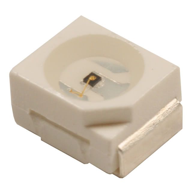
They are PLCC2 SMD LEDs.I had to look these up myself, just to make sure. Here's pictures of the two types so anyone looking to buy them will know what to look for.
PLCC2 SMD/SMT LEDs
1206 SMD/SMT LEDS

Reply 14 : DIY: Instrument Cluster LED
Great job, i wouldn't have balls to take it apart lol.
Great thoughts you got there, believe I may possibly try just some of it throughout my daily life.
ReplyDeleteInstrument Cluster